 | –≠–ª–µ–∫—Ç—Ä–æ–Ω–Ω—ã–π –∫–æ–º–ø–æ–Ω–µ–Ω—Ç: LM325 | –°–∫–∞—á–∞—Ç—å:  PDF PDF  ZIP ZIP |
LM325
Dual Voltage Regulator
General Description
This dual polarity tracking regulator is designed to provide
balanced positive and negative output voltages at current up
to 100 mA, and is set for
±
15V outputs. Input voltages up to
±
30V can be used and there is provision for adjustable cur-
rent limiting. The device is available in two package types to
accommodate various power requirements and temperature
ranges.
Features
n
±
15V tracking outputs
n
Output current to 100 mA
n
Output voltage balanced to within 2%
n
Line and load regulation of 0.06%
n
Internal thermal overload protection
n
Standby current drain of 3 mA
n
Externally adjustable current limit
n
Internal current limit
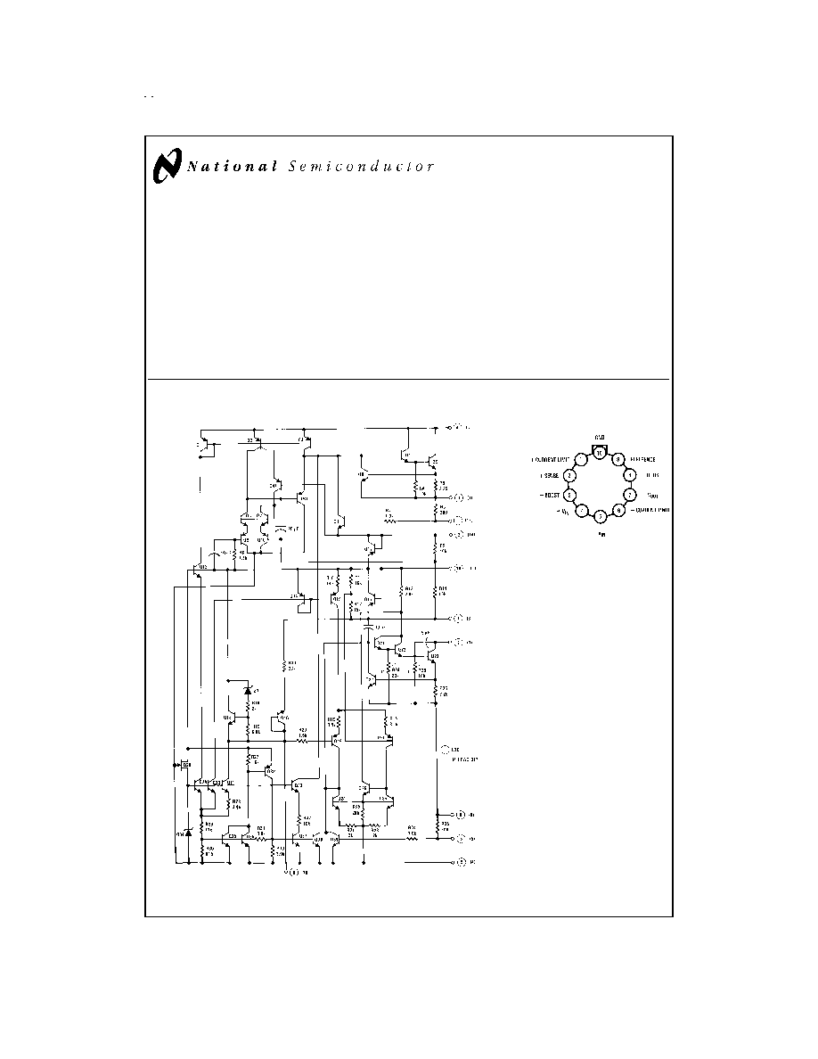
Schematic and Connection Diagrams
DS007776-1
Metal Can Package
DS007776-3
Case connected to -V
IN
Top View
Order Number LM325H
See NS Package Number H10C
June 1999
LM325
Dual
V
oltage
Regulator
© 1999 National Semiconductor Corporation
DS007776
www.national.com
Absolute Maximum Ratings
(Note 1)
If Military/Aerospace specified devices are required,
please contact the National Semiconductor Sales Office/
Distributors for availability and specifications.
Input Voltage
±
30V
Forced V
O
+
(Min) (Note 2)
-0.5V
Forced V
O
-
(Max) (Note 2)
+0.5V
Power Dissipation (Note 3)
P
MAX
Output Short-Circuit Duration (Note 4)
Continuous
Operating Conditions
Operating Free Temperature Range
0∞C to +70∞C
Storage Temperature Range
-65∞C to +150∞C
Lead Temperature (Soldering, 10 sec.)
300∞C
Electrical Characteristics
Parameter
Conditions
Min
Typ
Max
Units
Output Voltage
T
j
= 25∞C
14.5
15
15.5
V
Input-Output Differential
2.0
V
Line Regulation
V
IN
= 18V to 30V, I
L
= 20 mA,
T
j
= 25∞C
2.0
10
mV
Line Regulation Over Temperature Range
V
IN
= 18V to 30V, I
L
= 20 mA,
20
20
mV
Load Regulation
V
O
+
V
O
-
I
L
= 0 mA to 50 mA, V
IN
=
±
30V,
T =
j
25∞C
3.0
5.0
10
10
mV
mV
Load Regulation Over Temperature Range
V
O
+
V
O
-
I
L
= 0 mA to 50 mA, V
IN
=
±
30V
4.0
7.0
20
20
mV
mV
Output Voltage Balance
T
j
= 25∞C
±
300
mV
Output Voltage Over Temperature Range
P
P
MAX
, 0
I
O
50 mA,
18V
|V
IN
|
30
14.27
15.73
V
Temperature Stability of V
O
±
0.3
%
Short Circuit Current Limit
T
j
= 25∞C
260
mA
Output Noise Voltage
T
j
= 25∞C, BW = 100 - 10 kHz
150
µVrms
Positive Standby Current
T
j
= 25∞C
1.75
3.0
mA
Negative Standby Current
T
j
= 25∞C
3.1
5.0
mA
Long Term Stability
0.2
%/kHr
Thermal Resistance Junction to
Case (Note 5)
LM325H
Junction to Ambient
Junction to Ambient
(Still Air)
(400 Lf/min Air Flow)
20
215
82
∞C/W
∞C/W
∞C/W
Junction to Ambient
LM325N
(Still Air)
90
∞C/W
Note 1: "Absolute Maximum Ratings" indicate limits beyond which damage to the device may occur. Operating ratings indicate conditions for which the device is
functional, but do not guarantee specific performance limits.
Note 2: That voltage to which the output may be forced without damage to the device.
Note 3: Unless otherwise specified these specifications apply for T
j
= 0∞C to +125∞C on LM325, V
IN
=
±
20V, I
L
= 0 mA, I
MAX
= 100 mA, P
MAX
= 2.0W for the H10
Package.
Note 4: If the junction temperature exceeds 150∞C, the output short circuit duration is 60 seconds.
Note 5: Without a heat sink, the thermal resistance junction to ambient of the H10 Package is about 155∞C/W. With a heat sink, the effective thermal resistance can
only approach the junction to case values specified, depending on the efficiency of the sink.
www.national.com
2
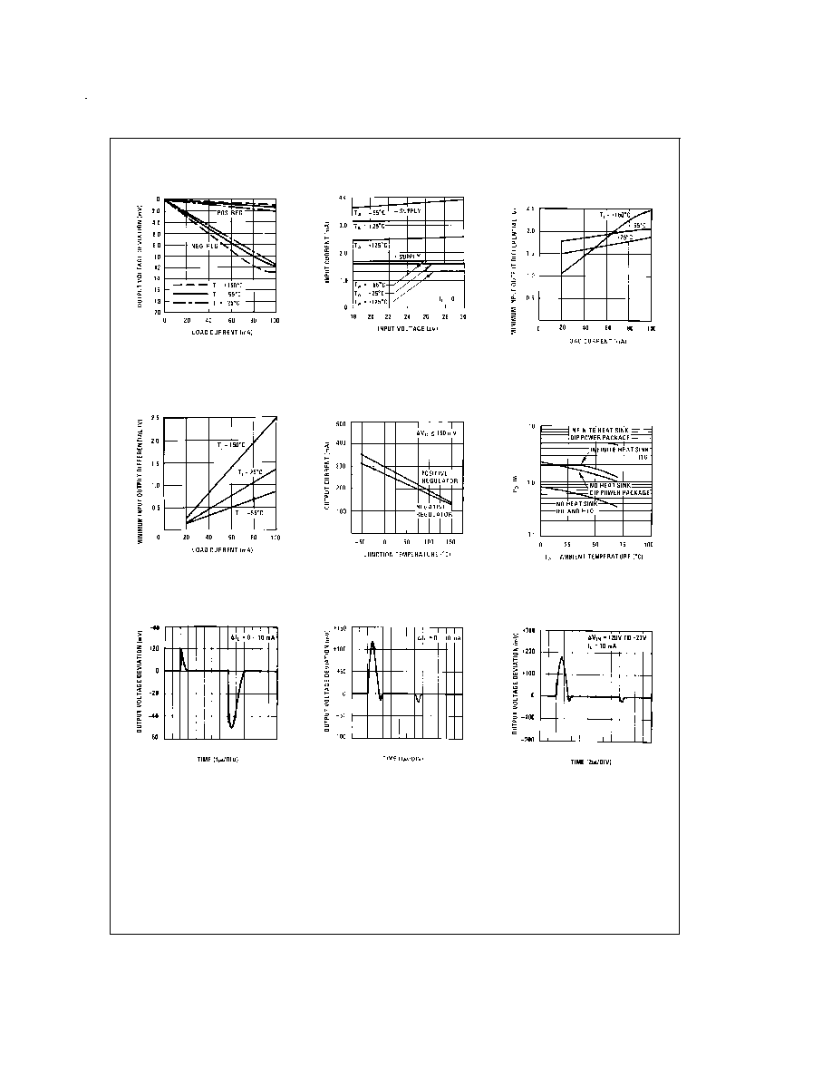
Typical Performance Characteristics
Load Regulation
DS007776-11
Standby Current Drain
DS007776-12
Regulator Dropout Voltage
for Positive Regulator
DS007776-13
Regulator
Dropout Voltage for
Negative Regulator
DS007776-14
Peak Output
Current vs
Junction Temperature
DS007776-15
LM325 Maximum Average
Power Dissipation vs
Ambient Temperature
DS007776-17
Load Transient Response
for Positive Regulator
DS007776-20
Load Transient Response
for Negative Regulator
DS007776-21
Line Transient Response
for Positive Regulator
DS007776-22
www.national.com
3
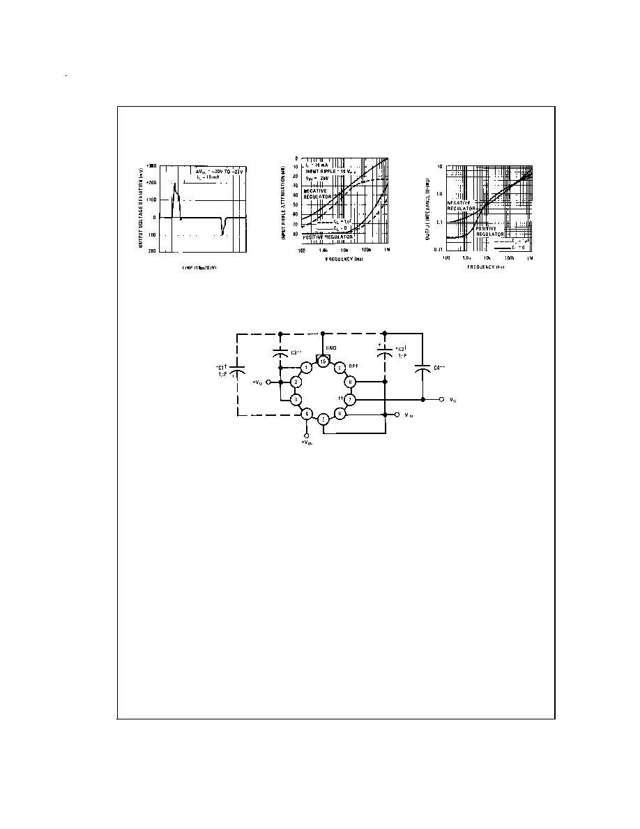
Typical Performance Characteristics
(Continued)
Typical Applications
Line Transient Response
for Negative Regulator
DS007776-23
Ripple Rejection
DS007776-24
Output Impedance
vs Frequency
DS007776-25
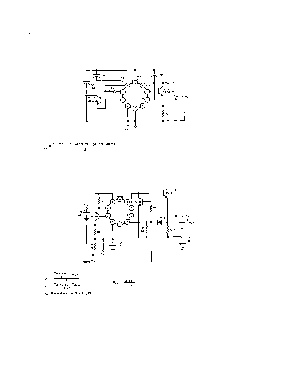
Basic Regulator
DS007776-6
www.national.com
4
Typical Applications
(Continued)
2.0 Amp Boosted Regulator with Current Limit
DS007776-7
Note: Metal can (H) packages shown.
Solid tantalum
Short pins 6 and 7 on dip
R
CL
can be added to the basic regulator between pins 6 and 5, 1 and 2 to reduce current limit.
*Required if regulator is located an appreciable distance from power supply filter.
*
*
Although no capacitor is needed for stability, it does help transient response. (If needed use 1 µF electrolytic.)
*
*
*
Although no capacitor is needed for stability, it does help transient response. (If needed use 10 µF electrolytic.)
Positive Current Dependent Simultaneous Current Limiting
DS007776-8
www.national.com
5